Red Blue Double Color Flashing Lights DIY Kit Strobe NE555 + CD4017 Electronic Practice Learning Kits Suite Parts Gift
Products information:
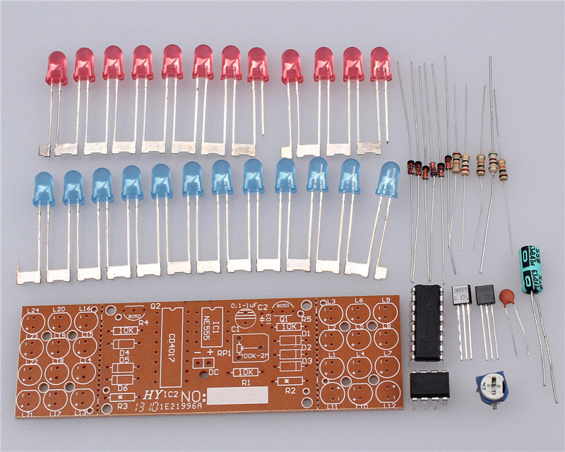
NOTE:There is no IC socket in kits. User can weld IC on PCB Directly.

Description
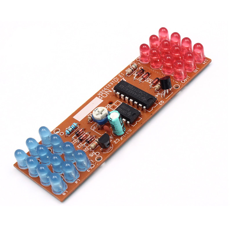
This suite adopts simulation light circuit made with NE555 and CD4017,the blue LED and red LED flashed alternately according to the pulse. The multivibrator composed of NE555 will have a certain frequency of oscillation signal send to CD4017 decimal counter/pulse distributor,in order to count. When the 1,3,5 pulses arrive Q0,Q2,Q4 output high level in turn,blue LED flashes 3 times,Q5,Q7,Q9 output high level in turn.Red LED flashes 3 times,blue LED flashes again when 11,13,15 pulses come,blue and red LED flashes alternately circulatory,so as to like the alarm lamp.Change the RP1 size can change the oscillation period, thus changing the LED shining speed, the whole circuit DC9-12V can be worked.
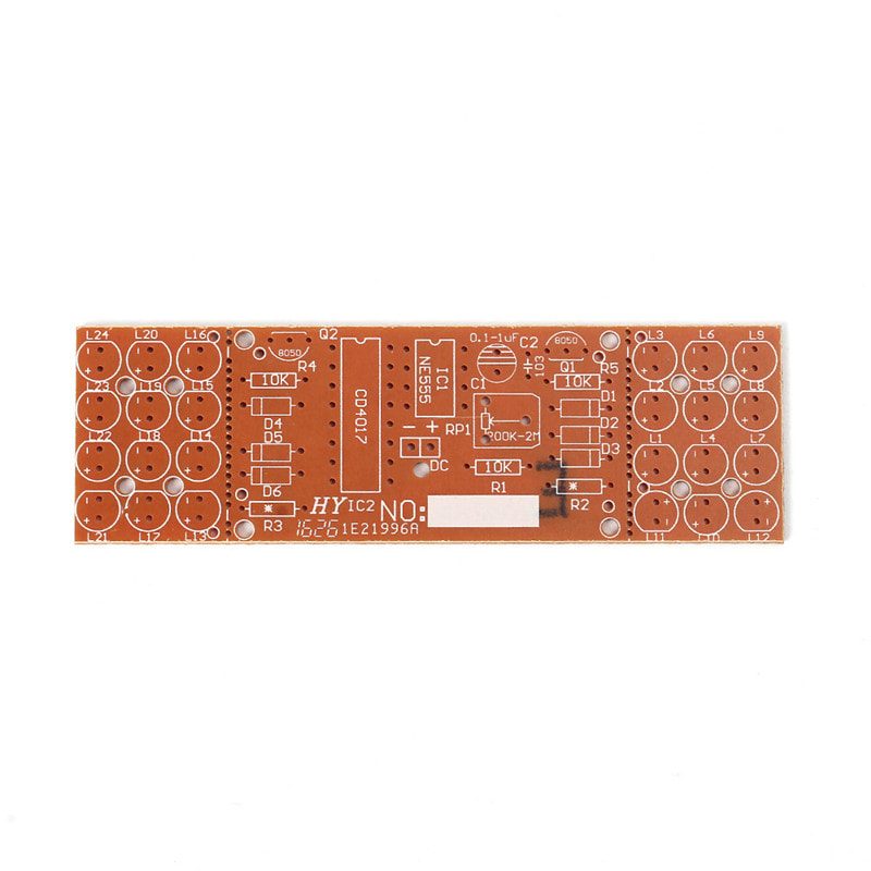
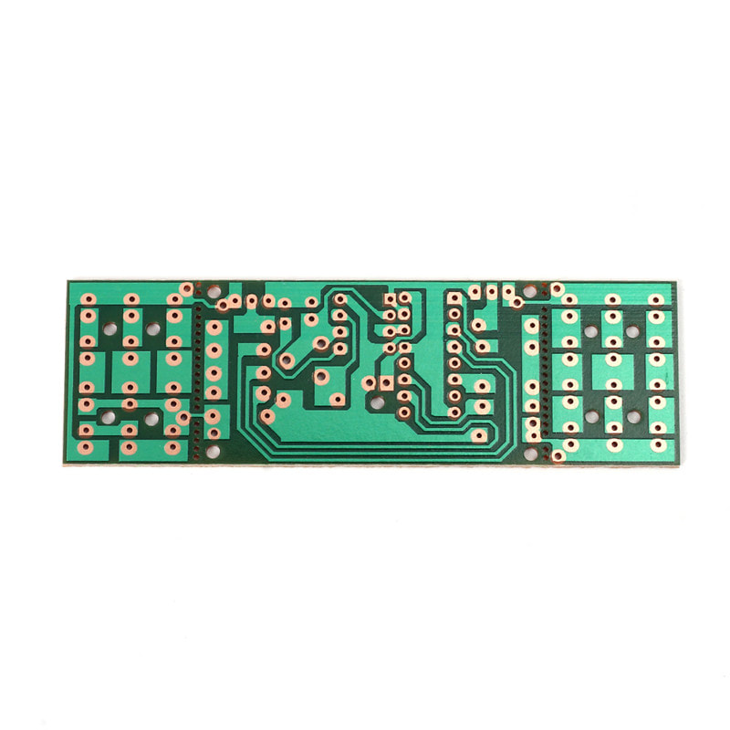
Red flashing light and blue flashing light form a board separately,connected with the main board through the stamp hole.If you need to install to other place separately or increase the distance,you should cut off through the stamp hole,then connect with the mother board by two wires.Please pay attention to the direction of LED when installing,especially the direction of L11 and L12.The R2 and R3 controls with the brightness of light,you can change it appropriately ,the range is 10-100 ohm.
supply power : 9-12V
This suite adopts simulation light circuit made with NE555 and CD4017,the blue LED and red LED flashed alternately according to the pulse. The multivibrator composed of NE555 will have a certain frequency of oscillation signal send to CD4017 decimal counter/pulse distributor,in order to count. When the 1,3,5 pulses arrive Q0,Q2,Q4 output high level in turn,blue LED flashes 3 times,Q5,Q7,Q9 output high level in turn.Red LED flashes 3 times,blue LED flashes again when 11,13,15 pulses come,blue and red LED flashes alternately circulatory,so as to like the alarm lamp.Change the RP1 size can change the oscillation period, thus changing the LED shining speed, the whole circuit DC9-12V can be worked.
Red flashing light and blue flashing light form a board separately,connected with the main board through the stamp hole.If you need to install to other place separately or increase the distance,you should cut off through the stamp hole,then connect with the mother board by two wires.Please pay attention to the direction of LED when installing,especially the direction of L11 and L12.The R2 and R3 controls with the brightness of light,you can change it appropriately ,the range is 10-100 ohm.
supply power : 9-12V
FREE SHIPPING TO WORLDWIDE
We ship your orders within 3 business days after the payment cleared.
Your item will be receive within 15 - 45. Delivery time depends on destination and other factors,If you do not receive your purchase within 60 days please contact us soon, we'll investigate and solve the delivery problem.
WE ONLY ACCEPT

RETURN POLICY
Return accepted for 30 days. If the product you receive is not as described or low quality, I promise that you may return it before order completion and receive a full refund. The return shipping fee will be paid by you.
OUR WORKING TIME
We will reply within 24 hours for your messages.
