Electronic Acoustic Clap Control Switch DIY Kit Sound Sensor Electronic Circuit DIY Suit
Products information:
NOTE : Read the description under photos before your weld circuit
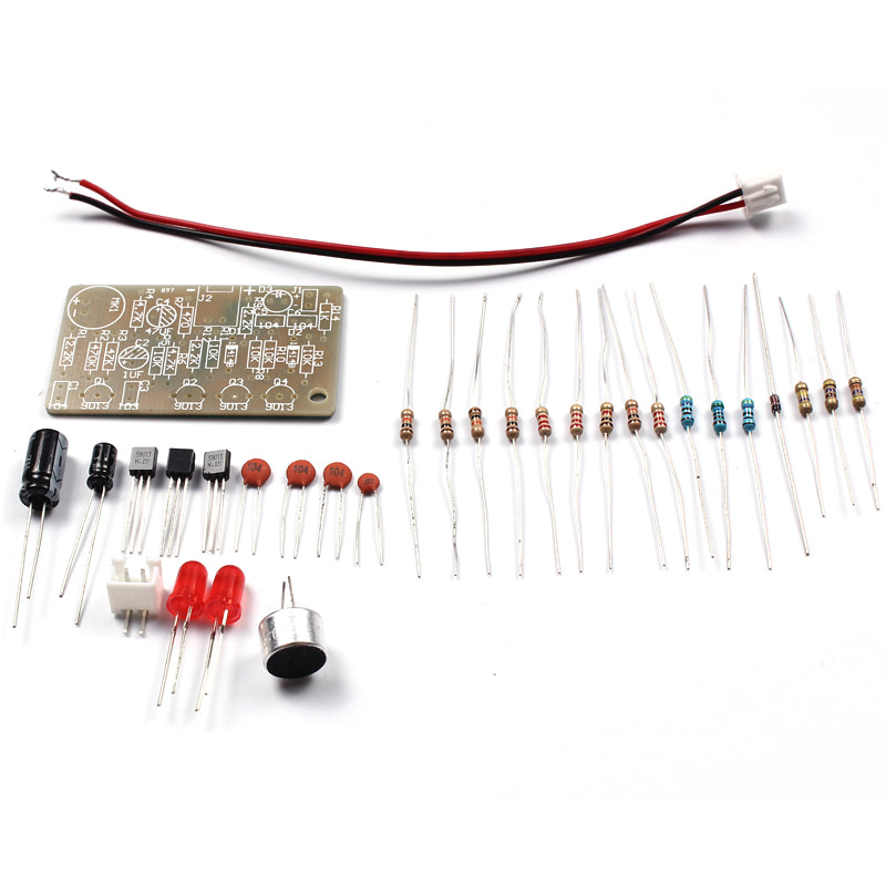
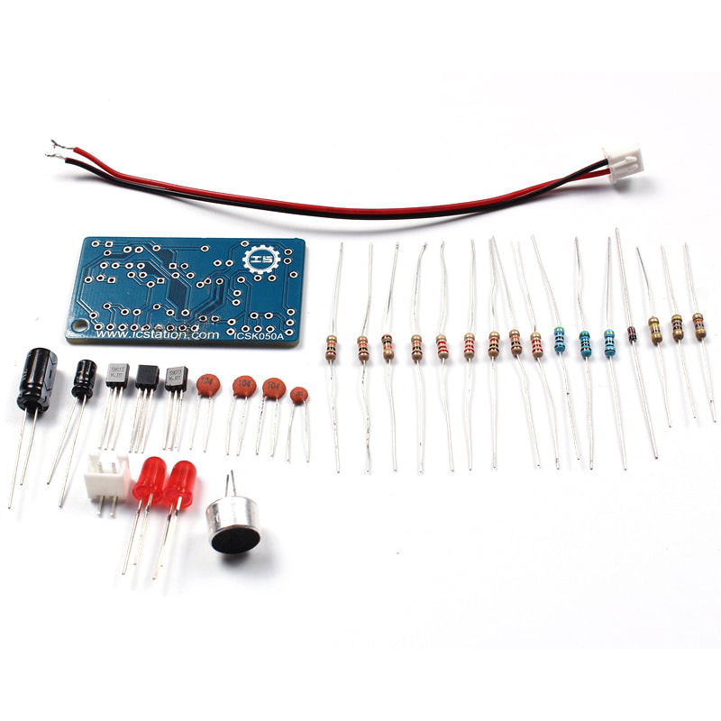
ICSK050A DIY Kits Clap Switch Suite Sound Sensor DIY Electronic Production
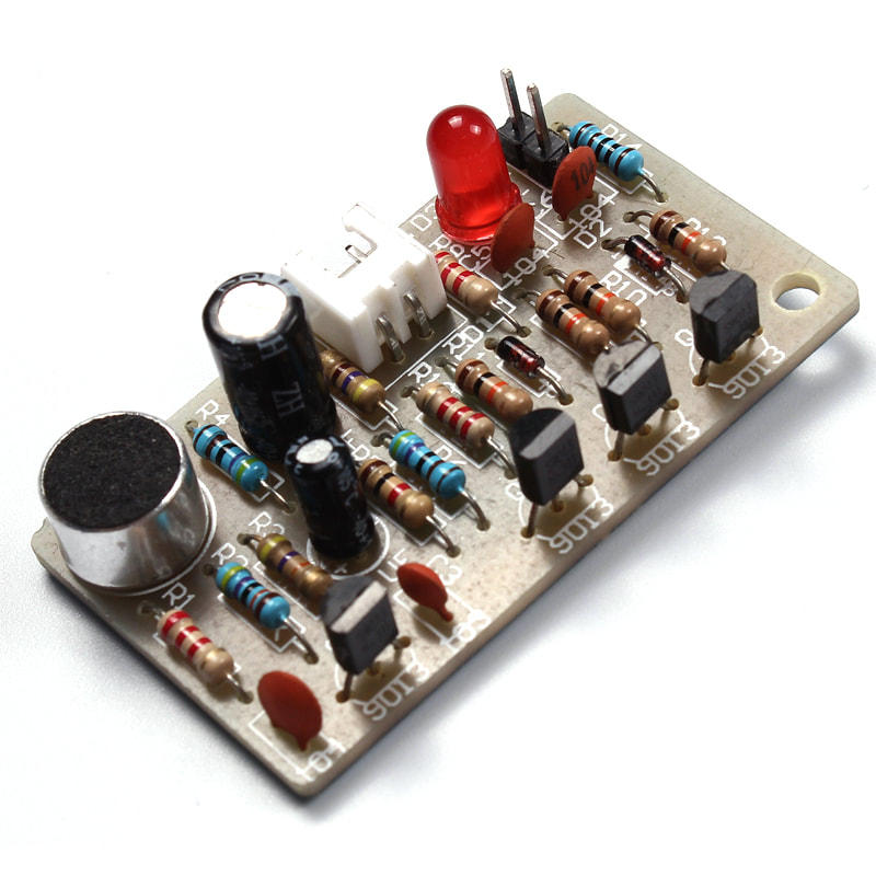
Clap switch kit is composed of resistors, capacitors and transistor amplifier circuit. The circuit is simple, welded easily, inexpensive, and widely used in voice-activated switch.
VCC: Connect 5V power supply positive (according to the relay voltage)
GND: Connect 5V power supply negative
IN: relay module signal trigger (low level active)
High and low meaning:
High-level trigger refers to the VCC side of the positive voltage and the trigger side of a trigger
When the trigger side has a positive voltage or to reach the trigger voltage, the relay is sucked.
Low-level trigger refers to the use of GnD side of the negative voltage and the trigger side of a trigger
When the trigger side OV voltage or voltage is low to trigger, the relay is pulled.
1. Characteristics
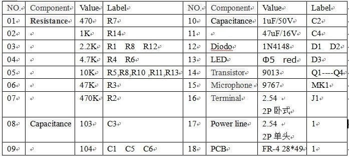
Operating voltage: 4.5 ~ 5V
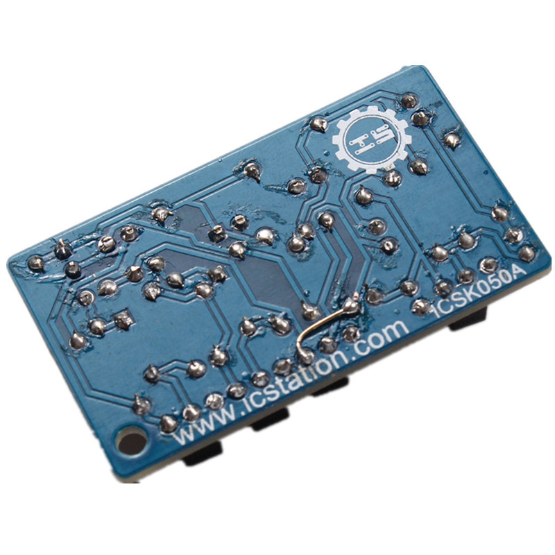
PCB size: 28 * 49mm
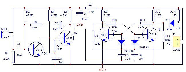
2. Circuit theory
This circuit is mainly assembled by the audio amplifier circuit and a flip-flop circuit.
Q1 and Q2 form a secondary audio amplifier, an audio signal received from MK1 C1 is coupled to the base of Q1, the amplification is fed directly from the collector to the base of Q2, the collector of Q2 to obtain a negative square wave with to trigger the bistable circuit. R1, C1 limit the frequency response of the circuit for the high sensitivity range of about 3kHz. When the power is turned on, the state of the bistable circuit is off Q4, Q3 saturated, D3 does not shine. When MK1 to a control signal output after the two-stage amplification of a negative square wave, after the differential processing by the negative spike D1 added to the base of Q3, the circuit rapidly inverted, D3 is illuminated. When MK1 again received control signal, the circuit took place flip, D3 extinguished. The board reserved for external control devices connected to terminals J1, can be a voice for other devices connected via J1 relay. (When connected to both ends of the relay coil relay to be anti and a diode)
This circuit uses a DC 5V power supply, turn off the machine when the LED current of 3 mA, the LED lights up the whole current of 6mA.
Clap switch kit is composed of resistors, capacitors and transistor amplifier circuit. The circuit is simple, welded easily, inexpensive, and widely used in voice-activated switch.
VCC: Connect 5V power supply positive (according to the relay voltage)
GND: Connect 5V power supply negative
IN: relay module signal trigger (low level active)
High and low meaning:
High-level trigger refers to the VCC side of the positive voltage and the trigger side of a trigger
When the trigger side has a positive voltage or to reach the trigger voltage, the relay is sucked.
Low-level trigger refers to the use of GnD side of the negative voltage and the trigger side of a trigger
When the trigger side OV voltage or voltage is low to trigger, the relay is pulled.
1. Characteristics
Operating voltage: 4.5 ~ 5V
PCB size: 28 * 49mm
2. Circuit theory
This circuit is mainly assembled by the audio amplifier circuit and a flip-flop circuit.
Q1 and Q2 form a secondary audio amplifier, an audio signal received from MK1 C1 is coupled to the base of Q1, the amplification is fed directly from the collector to the base of Q2, the collector of Q2 to obtain a negative square wave with to trigger the bistable circuit. R1, C1 limit the frequency response of the circuit for the high sensitivity range of about 3kHz. When the power is turned on, the state of the bistable circuit is off Q4, Q3 saturated, D3 does not shine. When MK1 to a control signal output after the two-stage amplification of a negative square wave, after the differential processing by the negative spike D1 added to the base of Q3, the circuit rapidly inverted, D3 is illuminated. When MK1 again received control signal, the circuit took place flip, D3 extinguished. The board reserved for external control devices connected to terminals J1, can be a voice for other devices connected via J1 relay. (When connected to both ends of the relay coil relay to be anti and a diode)
This circuit uses a DC 5V power supply, turn off the machine when the LED current of 3 mA, the LED lights up the whole current of 6mA.
FREE SHIPPING TO WORLDWIDE
We ship your orders within 3 business days after the payment cleared.
Your item will be receive within 15 - 45. Delivery time depends on destination and other factors,If you do not receive your purchase within 60 days please contact us soon, we'll investigate and solve the delivery problem.
WE ONLY ACCEPT

RETURN POLICY
Return accepted for 30 days. If the product you receive is not as described or low quality, I promise that you may return it before order completion and receive a full refund. The return shipping fee will be paid by you.
OUR WORKING TIME
We will reply within 24 hours for your messages.
